“How accurate is 3D photogrammetry model without Ground Control Points?” This question is often asked by our customers but there was never a definitive answer, until now.
But first some background on Ground Control Points (GCP) and why they are used. GCP’s are currently used by SiteSee to ensure both accuracy scale and orientation of 3D models of cell towers. GCP are static markers that accurately identify a point on the earth’s surface. These markers are typical using GPS with a correction network to provide very accurate static positioning. In the photogrammetry processing these markers are identified in the imagery and given an accurate 3D position. The bundle adjustment is now constrained by these fixed points, allowing for a more accurate 3D model.
The 3D model characteristics of dimension scale and angle are important for the SiteSee automated object recognition system. The scale determines the size of each of the three dimensions. For cell towers the most important dimension is along the vertical (z axis), as the height of the cell tower equipment is one of the most important measurements. The orientation of the cell tower allows for accurate absolute bearings and tilts of equipment.
This accuracy comparison will use a single acquisition data set of a cell tower. The only difference between the photogrammetry results is one processed with GCP the other without, allowing for a simple comparison.
This experiment is not meant to be an exhaustive exercise in surveying. But rather a short, sharp determination of the suitability of the SiteSee photogrammetry model’s accuracy without GCP compared to using GCP. It will measure points between two identical elements of a Telco lattice tower on two 3D models prepared by SiteSee using Photogrammetry, UAV and with/out GCP. In a previous article the high relative accuracy of the photogrammetry with GCP a Lieca Laser Scanner has been demonstrated. http://www.sitesee.io/news/2018/3/12/photogrammetry-verus-lidar-accuracy. Hence the reference dimensions will be from 3D model with GCP.
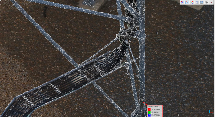
The two model elements being measured are; a) underside of a gantry (Figure 1) to b) the underside of the steel resting on the footing (Figure 2).
Although there is three dimensions of each point, however this experiment is concerned with the major dimension of the telco tower, the vertical or z dimension.
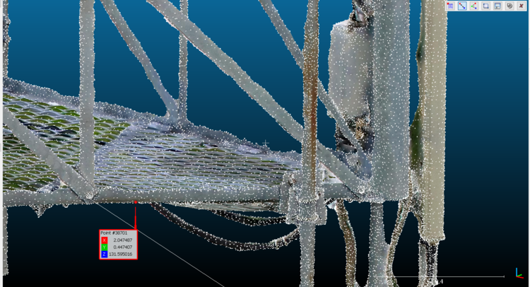
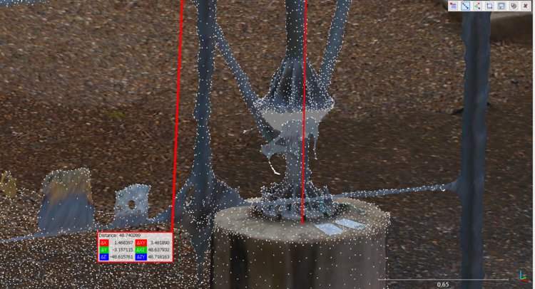
Target: Telco Tower, Pullenvale Brisbane Australia
Photogrammetry: DJI Phantom 4Pro, 5xPropeller Aeropoints, Context Capture v4.4.8.561.
Photogrammetry: DJI Phantom 4Pro, NoGCP, Context Capture v4.4.8.561.
.obj mesh model.
Measurement software: CloudCompare V2.91 64bit.
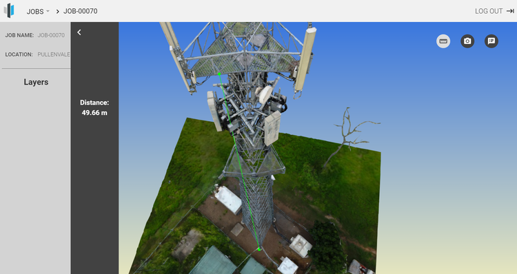
Acquisition Background
The tower was flown with a DJI phantom P4, using the Drome Harmony autopilot app. Propeller Aero points were used to for Ground Control Points (GCP). The flight plan follows SiteSee proprietary vertical structure flight plan. Approximately 1500 images were captured. ContextCapture was used to perform the photogrammetry. No manual tie points were used. The resulting model was a mesh in OBJ format with texture.
The comparison of using GCP versus not using GCP will be performed using the data used in the above but without the GCP included in the Aero Triangulation phase of the photogrammetry processing.
RESULTS
SCALE RESULTS
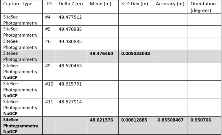
The scale accuracy results shown in Table 1, demonstrate a difference of -0.855m over 50m between the GCP and No GCP models. This figure seems surprisingly low. However, when considering that majority of cell tower equipment is located at the top of the tower, the error in the equipment is significant.
ORIENTATION RESULTS
To determine relative orientation between the models, points along an external member will be used See Figure 4. Points will be selected on the outside of the member, one near the base the other near the top. This will allow the comparison of the orientation of the same external member between models.
Using the “dot product” below; calculates the smallest angle between the vectors that describe the external member.

The result is a surprising
WRAP UP
The comparison of a photogrammetry model reconstruction using GCP vs NoGCP has produced reasonable accuracy based on measures of scale and orientation. The scale difference will become an issue for any accurate vertical measurement such as Telco towers. The orientation difference seems to be far less and may not be that significant for some applications.
However, for automated object recognition these accuracy differences mean that GCP will still be used for data acquisition and processing, to ensure accurate “As-built” of Telco assets.
2 Likes


