The future of EME simulation and compliance
In our modern society mobile phones and radio communications are part of everyday life. In Australia, mobile network communications are regulated by the Australian Communications and Media Authority (ACMA). The ACMA takes it’s advice from the Australian Radiation Protection and Nuclear Safety Agency (ARPANSA) who set the safety standards.
It is essential for each transmitting device to demonstrate that it is safe for people in the environment. The compliance of this demonstration of safety has its own industry that focuses on various methods for compliance including both measurement and numerical modelling of the electromagnetic energy (EME).
Is there a way to improve the demonstration of this compliance? Let’s discuss the modelling technique and how to employ it to accurately simulate mobile network EME in a 3D environment.
Modelling Accuracy
The overall transmitted intensity field in a scene is dependent on two main inputs: base station antenna information (make, model, position, etc) and the environment (trees, power lines, structures, etc). Through modern technology, the opportunity exists to perform EME calculations within a reality captured scene to provide improved EME “exclusion zone” (areas of unsafe radiation) simulations.
Current safety compliance modelling uses high quality far field simulations for EME propagation, but it is decoupled from the actual antenna and its environment. Each antenna's position and its neighbouring antennas are aggregated to form the total intensity field. Accuracy is limited by our knowledge of the antennas location in the scene and is currently compensated for by including additional uncertainty which is propagated through the EME exclusion zone calculation.
EME Simulation
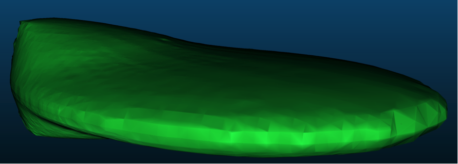
Modern algorithms can be used to estimate EME exclusion zones. They typically include full-wave simulations, where the electric and magnetic fields are simulated carefully considering all aspects of the scene, or far-field estimations (visualised in figure 1), where simplifying assumptions can produce satisfactorily accurate estimations.
These methods use the specific radiation pattern of each antenna to produce an occupational safety zone for a group of antennas. These methods are well respected and documented in various standards, however the estimated zones and their uncertainty are only as accurate as the input data.

EME visualisation
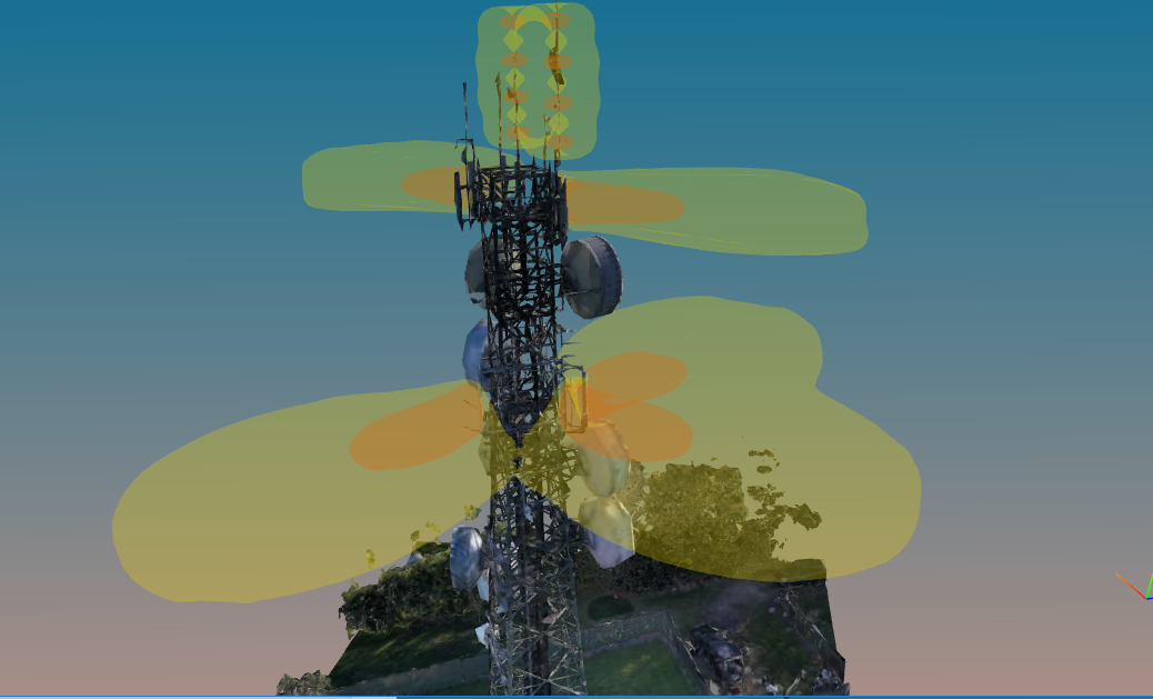
The tower, its antennas and the surrounding environment can all be captured in 3D using reality capture techniques such as photogrammetry or LIDAR. This reality captured model becomes the point of truth: removing approximations of antenna locations or estimations of the environment. RF assessors and personnel can understand exactly where antennas and their EME exclusion zones exist within reality captured environment, as shown in figure 2.
This 3D reality model is the basis for all user interaction and can be interrogated by the user with 3D visualisation.

EME Collision Detection
Current methods for validating EME separation requirements involve manual measurements. Combining the 3D reality captured scene with an in situ EME simulation, we now have an innovative alternative. Collisions between EME exclusion zone boundary and the environment can be highlighted and visualised easily, enabling rapid assessment and assurance that no objects in the environment are missed.
Going Forward
Accurate reality mapped environments combined with EME simulation reduces uncertainty and assessment time, whilst providing superior assessment and peace of mind for personnel working in the presence of RF radiation.


